SAM E51 Curiosity Nano programming with Zig #1
This series of posts is inspired by the Rust Discovery Book, a great learning resource on how to program microcontrollers using Rust. We’re going to program the SAM E51 Curiosity Nano using the Zig programming language, which is new and not quite production ready so be prepared to encounter some breaking changes.
Introduction
Scope
Eventually, the following topics will be covered:
- How to write, build and flash an “embedded” (Zig) program using MicroZig, Regz and Microchip Studio (flashing).
- Functionality (“peripherals”) commonly found in microcontrollers like:
- digital input and output
- pulse width modulation (PWM)
- analog to digital converters (ADC)
- common communication protocols like:
- U(S)ART
- I2C
- Multitasking concepts:
- cooperative vs preemptive multitasking
- interrupts
- schedulers
- Cryptography
Approach
- As much as possible beginner friendly, but because there are no existing resources for the ATSAME51J20A chip we need to set up everything ourselves.
Non-goals
What’s out of scope for this series of posts:
- Teaching Zig. We’ll focus on programming microcontrollers.
- Being a comprehensive text about electric circuit theory or electronics.
Note: This book will make exclusive use of the SAM E51 Curiosity Nano. Because we’re going to use Microchip Studio to flash the device, you need a Windows PC. I haven’t found a good tool for Linux yet.
Reporting problems
The source of this book is in this repository. If you encounter any typo or problem with the code, please report it on the issue tracker.
Other embedded Zig resources
The Zig Embedded Group offers more learning material on programming embedded devices and maintains the libraries (MicroZig and Regz) we’re going to use throughout this course.
Background
What’s a microcontroller?
A microcontroller is a system on a chip (SOC). Whereas your computer is made up of several discrete components: a processor, RAM, storage, an Ethernet port, etc.; a microcontroller has all those types of components built into a single chip. This makes it possible to build systems with fewer parts.
Why use Zig and not C or Rust?
Because you’re interested in Zig and microcontrollers. Honestly, there aren’t many reasons at the moment. You’ll encounter breaking changes because the language is still in development and there are almost no Zig frameworks/ tools for programming microcontrollers at the moment. If you want to create the next big thing, you’ll probably want to stay away from Zig at the moment.
Requirements
The primary requirement to read this series of posts is to know some Zig, i.e. to be at least somewhat comfortable with structs, pointers, and arrays.
Also, to follow this material you’ll need the following hardware:
- A SAM E51 Curiosity Nano using the Zig board (You can purchase this board from several electronic suppliers).
- A micro-B USB cable, to connect the Curiosity Nano to your computer. The cable must support data transfer.
FAQ: Can I follow this guide with a different development board?
Probably. While there are many different boards and processors, the general concepts stay similar. If you choose a different board, you’ll need the datasheets for the development board and processor, e.g. to lookup addresses.
Setting up a development environment
Because Zig supports cross-compilation out of the box, i.e. compiling code for an architecture that differs from the one you’re developing on, we don’t need to install any additional toolchains. Nevertheless, we still need some things before we can get started.
Documentation
Without documentation, it’s pretty much impossible to work with microcontrollers. We’ll be referring to the following documents throughout this book:
Tools
We’ll use the tools listed below.
- Zig (DEV NOTE: freeze at v10.0 as soon as released)
- Git
- MicroZig
- Regz
- Microchip Studio
Note: You can execute all stated instructions in a Shell/ PowerShell.
Zig
To install Zig you can follow the official getting started guide.
MicroZig
When it comes to MicroZig we’re left with two options. We can either add it directly as a submodule to our project or fork it and add our fork as a submodule. I’ll use the latter option because I’m going to make some changes to the library.
Regz
To install Regz just clone the project using Git and build it with Zig.
git clone https://github.com/ZigEmbeddedGroup/regz.git
cd regz
zig build
You can consider this a test that you’ve installed Zig correctly. Zig will place the binary in zig-out/bin/regz.
Microchip Studio
Just download the installer from the website and execute it.
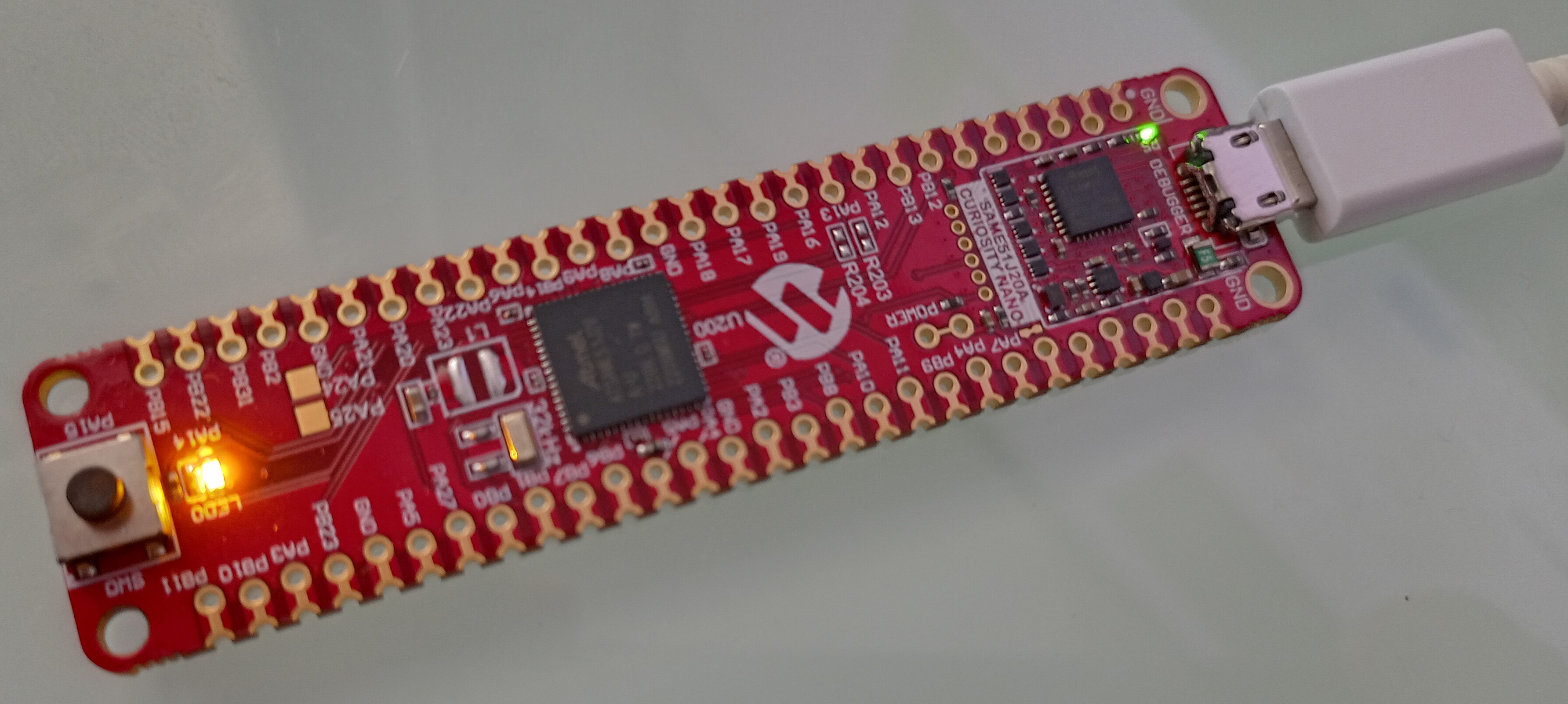
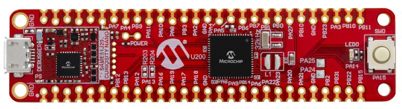
Meet your hardware
The SAM E51 Curiosity Nano evaluation board contains the following components:
- A microcontroller (SAME51J20A)
- Two LEDs (User LED and Power/Status LED)
- A User Switch (Button)
- A Debugger
- One USB port
Of these components, the most important is the microcontroller (MCU), which is the big black square in the middle of the board. The MCU is what runs your code. When we talk about “programming a board”, in reality, we mean programming the MCU that is part of the board. Let’s take a closer look at the MCU.
SAME51J20A
The name of our MCU seems random at first but it contains a lot of information about its characteristics. SAM stands for Smart ARM Microcontroller (the product familiy), E51 tells you that the MCU is a ARM Coretex-M4F (advanced feature set + 2x Controller Area Network (CAN)), J means that the MCU has 64 Pins in total (which we’re going to control soon), 20 tells you that the MCU has 1 MB of flash memory for storing your program and A stands for default variant.
The chip is packed with different “peripherals”, i.e. building blocks that enable the MCU to fulfill different tasks like doing cryptography in hardware or talking to a computer using a serial interface. We’ll look at some of those peripherals in the future.
Set up the project
Before we can start programming, we need to set up our project. I’ll guide you through the steps necessary to add support for a new chip to the MicroZig library. Create a new folder and execute the following command within:
zig init-exe
Your project folder should now contain the following files:
build.zig- contains the build script for your projectsrc/main.zig- contains the main function (the entry point of your program)
The MicroZig library offers help when it comes to building the project and generalized interfaces for GPIO and peripherals. Create a new folder called libs and add MicroZig as a submodule.
Note: You may want to fork MicroZig and add your fork as a submodule.
cd libs
git submodule add https://github.com/ZigEmbeddedGroup/microzig.git
MicroZig supports a variety of chips (see microzig/src/modules/chips). To add support for our SAME51J20A chip, we add a new folder to microzig/src/modules/chips called atsame51j20a which will contain the chip-specific Zig code.
Generate Zig code from an SVD file
Vendors often publish files that describe the special function register layout of a microcontroller called System View Description (SVD). The Regz tool can translate an SVD file into Zig code that can be used with libraries like MicroZig to gain access to special function registers, e.g. the Port. Download the ATSAME51J20A.svd file and then use Regz to translate it into Zig code.
regz ATSAME51J20A.svd > microzig/src/modules/atsame51j20a/registers.zig
Note: I found a issue with Regz, where the tool translates addresses into numbers of type
comptime_int. If you encounter an error likeerror: expected pointer, found 'comptime_int'use@intToPtrto cast the numbers to pointers, e.g. modifypub const base_address = 0x41008000topub const base_address = @intToPtr([*]u8, 0x41008000).Update: The issue has been fixed.
Now let’s look at how the generated file is structured.
The file contains one large struct called registers which itself contains a lot of nested structs. Most of those nested structs represent either a peripheral like a port, serial interfaces, or other important memory-mapped registers to control the behavior and functionality of the chip.
The microcontroller we’re working with has 64 Pins split into two groups A and B with 32 Pins each. We can control each pin by manipulating the PORT (I/O Pin Controller) at address 0x41008000 (Port A) and 0x41008000 + 0x80 (Port B).
pub const registers = struct {
    // ...

    /// Port Module
    pub const PORT = struct {
        pub const base_address = @intToPtr([*]u8, 0x41008000);
        pub const version = "U22102.2.0";

        // ...
    }

    // ...
}
Each nested struct starts with a base_address definition which defines the address in memory at which the group of registers that make up the peripheral can be found. To get an overview of the memory mapping check out the datasheet on page 51.
 pub const GROUP = @ptrCast(*volatile [2]packed struct {
    /// Data Direction
    DIR: u32,

    /// Data Direction Clear
    DIRCLR: u32,

    /// Data Direction Set
    DIRSET: u32,

    // ...

}, base_address);
The base address, plus an optional offset, is then cast to a struct that represents one or multiple registers in memory. This makes it easier to work with peripherals because you’re able to reference specific memory regions by name. In the example above the base_address is cast to an array called GROUP of two structs, where the first struct (index 0) represents port group A (PA) and the second represents port group B (PB).
Say you want to set pin 14 of port group A (PA14) as output. To accomplish that you can access the first element of GROUP and write a 1 into bit 14 of the DIRSET register, i.e. registers.PORT.GROUP[0].DIRSET = (1 << 14). This is much better than writing something like *(int*)(41008000 + 8) = (1 << 14) because you can express your intentions more clearly.
One important thing to note is, that the nested structs represent an idealized version of the register layout, i.e. multiple structs can represent the same memory region (share the same address and size in memory), and the decision on which struct to use depends on the context you’re working in.
Defining the Chip
Next, we’ll write some Zig code for the ATSAME51J20A. Create a new file in microzig/src/modules/chips/atsame51j20a called atsame51j20a.zig and paste the following code:
// microzig/src/modules/chips/atsame51j20a/atsame51j20a.zig

pub const cpu = @import("cpu");
pub const micro = @import("microzig");
pub const chip = @import("registers.zig");

const regs = chip.registers;
pub usingnamespace chip;

pub const clock_frequencies = . {
    .cpu = 120_000_000, // Arm Cortex-M4 runs at 120 MHz
};
We import the register file we created in the last section as chip and assign the chip.registers constant to a new constant called regs so we don’t have to write so much. Also, we define the cpu clock frequency to be 120MHz.
The remaining goal of this chapter is to blink the status led (PA14). To make that happen we’re going to use the existing PIN and GPIO interface of microzig. Let’s start with the pin.
The function microzig.Pin takes a string of the form P{port}{number} and returns a anonymous struct that represents the given pin. This pin-wrapper is then used as argument by other functions, e.g. the GPIO functions we’ll implement soon. microzig.Pin expects each chip to implement the parsePin function.
// microzig/src/modules/chips/atsame51j20a/atsame51j20a.zig

/// Get access to the pin specified by `spec`.
///
/// - `spec`: P{port}{pin}
///     - `port`: A, B
///     - `pin`: 0..31
pub fn parsePin(comptime spec: []const u8) type {
    const invalid_format_msg = "The given pin '" ++ spec ++ "' has an invalid format. Pins must follow the format \"P{Port}{Pin}\" scheme.";

    if (spec[0] != 'P')
        @compileError(invalid_format_msg);
    if (spec[1] < 'A' or spec[1] > 'B') // J = 64 Pins; 2 Ports
        @compileError("Unknown port '" ++ spec[1..2] ++ "'. Supported ports: A, B.");

    return struct {
        // Try to parse the given pin number as u5, i.e. a value in '0'..'31'.
        const pin_number: u5 = @import("std").fmt.parseInt(u5, spec[2..], 10) catch @compileError(invalid_format_msg);
        const pin_mask: u32 = (1 << pin_number);
        // Port is either 'A' or 'B'.
        const port_number: usize = if (spec[1] == 'A') 0 else 1;
        const gpio_port = @field(regs.PORT, "GROUP");
    };
}
The parsePin function first checks that the specified port group and pin number are valid, and then returns a anonymous struct containing information about the pin. This includes a reference to the port, the port number, and a mask so we can set some pin-specific registers more easily. Now let’s implement the required I/O functions to toggle the LED.
// microzig/src/modules/chips/atsame51j20a/atsame51j20a.zig

pub const gpio = struct {
    // See SAM D5x/E5x Family Data Sheet page 807.

    /// Configure the given pin as output with input disabled.
    pub fn setOutput(comptime pin: type) void {
        // To use pin Pxy as an output, write bit y of the DIR register to '1'. This
        // can also be done by writing bit y int the DIRSET register to '1' - this
        // will avoid disturbing the configuration of other pins (datasheet p. 803).
        pin.gpio_port[pin.port_number].DIRSET = pin.pin_mask;
        // Disable input for the given pin.
        pin.gpio_port[pin.port_number].PINCFG[pin.pin_number].modify(.{.INEN = 0});
    }

    pub fn write(comptime pin: type, state: micro.gpio.State) void {
        switch (state) {
            .high => pin.gpio_port[pin.port_number].OUTSET = pin.pin_mask,
            .low => pin.gpio_port[pin.port_number].OUTCLR = pin.pin_mask,
        }
    }

    pub fn toggle(comptime pin: type) void {
        pin.gpio_port[pin.port_number].OUTTGL = pin.pin_mask;
    }
};
We define setOutput so we can configure the direction of a pin as output. One can configure the i’th pin of a port group as output by setting bit i of DIRSET to 1. The alternative would be to manipulate DIR directly but then you must be careful to maintain the state of the other pins.
Setting a pin as high/ low is as easy as setting the i’th pin of the OUTSET/ OUTCLR register to 1. Like before you can also write to the OUT register directly. The write function takes a pin and a state (.high or .low) and writes to the associated register.
Now let’s define the chip itself as a public constant named atsame51j20a in microchip/src/modules/chips.zig.
// microzig/src/modules/chips.zig

pub const atsame51j20a = Chip{
    .name = "ATSAME51J20A",
    .path = root_path ++ "chips/atsame51j20a/atsame51j20a.zig",
    .cpu = cpus.cortex_m4,
    .memory_regions = &.{
        // SAM D5x/E5x Family Data Sheet page 53
        MemoryRegion{ .offset = 0x00000000, .length = 1024 * 1024, .kind = .flash },
        MemoryRegion{ .offset = 0x20000000, .length = 256 * 1024, .kind = .ram },
    },
};
The definition includes the name of the chip, as well as the path to our atsame51j20a.zig file. As CPU we select cortex_m4 so that Zig knows for which architecture an ATSAME51J20A program should be compiled. cortex_m4 also defines, among other things, some CPU-specific startup code (clear the .bss section with zeroes, load the program from flash, …). The memory regions are taken from the data sheet of the ATSAME51J20A and tell Zig where the flash (the place where our program is stored on the chip) and ram are located.
Now, the only thing left is our main function.
Blinking a LED
The remaining code to blink a LED is actually quite simple. Let’s take a look and see how it works.
const micro = @import("microzig");

const status_led_pin = micro.Pin("PA14");

pub fn main() void {
    const status_led = micro.Gpio(status_led_pin, .{
        .mode = .output,
        .initial_state = .high,
    });
    status_led.init();

    while (true) {
        busyloop();
        status_led.toggle();
    }
}

fn busyloop() void {
    const limit = 5_000_000;

    var i: u32 = 0;
    while (i < limit) : (i += 1) {
        @import("std").mem.doNotOptimizeAway(i);
    }
}
At the top, we define a new status_led_pin (PA14) which is connected to the status LED of our board. The Pin function calls our parsePin function we defined earlier. Then we pass that pin to the Gpio function together with some options to set the pin as output with an initial state of high. The struct returned from Gpio is a wrapper that connects our status_led_pin to the GPIO functions we defined in atsame51j20a.zig but also offers additional functionality.
To actually initialize our status_led we must call the init function on it which will indirectly call the setOutput and write function we defined.
Note: I’d advice to read through
gpio.zigandpin.zigto get a better understanding on what’s going on under the hood.
The rest of the code is trivial. We define the main loop of our program which contains exactly two instructions. Each turn we wait for a short period of time by wasting CPU cycles using the busyloop function. After that we toggle the PIN, i.e. if the pin is high we set it to low and vice versa.
Build it
Building our project is quite easy.
// build.zig

const std = @import("std");
const microzig = @import("libs/microzig/src/main.zig");

pub fn build(b: *std.build.Builder) void {
    const backing = .{
        .chip = microzig.chips.atsame51j20a,
    };

    const exe = microzig.addEmbeddedExecutable(
        b,
        "my-program",
        "src/main.zig",
        backing,
        .{
            // optional slice of packages that can be imported into your app:b
            // .packages = &my_packages,
        }
    );

    exe.inner.setBuildMode(.ReleaseSmall);
    exe.inner.strip = true;
    exe.inner.install();
}
We can leverage the addEmbeddedExecutable function of MicroZig to save us some work. All it takes is a backing (our chip), the name of our program, the path to our main function, and some optional packages to include.
To build the executable just enter zig build on the command line. If everything goes well you can find your executable in zig-out/bin/.
Flash it
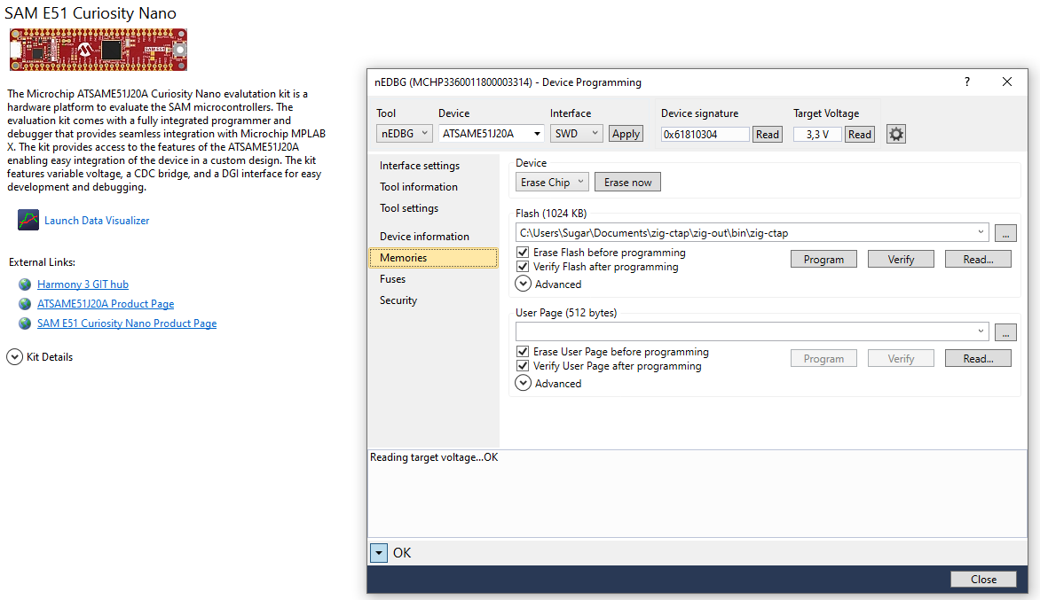
Microchip Studio (Windows)
Open Microchip Studio and connect the board to your Computer using a USB cable. Then press Ctrl + Shift + P to open the Device Programmer. Select your device and then press the Apply button. Open the Memories tab and press the [...] button of the Flash section to select your program located in your-project/zig-out/bin. Finally, press Program to flash your device.
EDBG (Linux, Mac, Windows)
The CMSIS-DAP programmer (EDBG) works on Linux, Mac and Windows.
Besides the program itself you’ll need a tool like arm-none-eabi-objcopy to
extract the binary content from the executable (e.g. ELF) generated by zig build.
On Ubuntu you can run
sudo apt install binutils-arm-none-eabi.
Connect the board to your Computer using a USB cable. You can verify that the onboard debugger has been recognized using the following command:
$ edbg -l
Attached debuggers:
  0: MCHP3360011800003314 - Microchip Technology Incorporated nEDBG CMSIS-DAP
Then build your project and extract the binary content.
$ zig build && arm-none-eabi-objcopy -O binary zig-out/bin/your-program kernel.bin
Last but not least use EDBG to upload your program.
$ sudo edbg -b -t same51 -pv -f kernel.bin
Debugger: Microchip nEDBG CMSIS-DAP MCHP3360011800003314 00.01.0000 (S)
Clock frequency: 16.0 MHz
Target: SAM E51J20A (Rev D)
Programming.... done.
Verification....... done.
After a few seconds, you should see a blinking LED next to the push button.